Drilling Rig Automation & Control System | Drive Technology
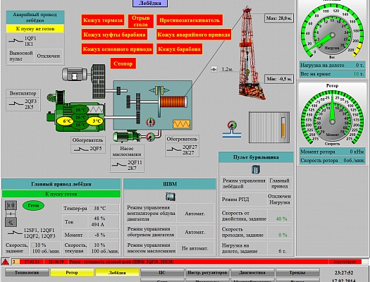


Automated control system
Purpose:
It is intended for controlling the electric drives of the main (drilling pumps, winch and rotor) and auxiliary mechanisms of the drilling rig in manual or semi-automatic mode, developed on the basis of a microprocessor-based programmable controller and performs the following functions:
- input, control and primary processing of input signals;
- control over the output of parameter values for the allowed technological boundaries, serviceability of sensors and communication lines;
- collection, processing and visualization of information on the state of equipment, sensors and communication lines;
- control of the rig's mechanisms in accordance with the required regimes;
- reception and control of the reliability of manual input information;
- generation and issuance of control actions and reports of failures and deviations of parameters;
- calculation of the operating time of the main equipment.
The ACS system includes the following equipment:
- cabinet with microprocessor controller - IPC;
- Driller console - PB;
- control panel for drilling pumps - PN;
- cabinet AKL with remote information input / output station;
- Inverters (drive units) with digital control IN1 ... IN4.
The cabinet AKL with remote information input / output station is installed in the winch unit of the drilling rig.
The driller's console with a graphic display and control buttons, as well as a commanding device connected to the console for setting the speed of the winch, is located in the driller's cabin.
The pump control panel with remote information input / output station is installed in the pump unit.
The main mechanisms of the drilling rig are controlled from the driller's console via the Profibus DP network. On the console of the driller, the state of the main drives is visualized.
When developing the control system, the principle of modularity and interchangeability of the elements of the system was used. Restoration of system serviceability in case of failures is made, as a rule, by replacing the elements with similar ones from the spare parts kit. This principle of building the system makes it possible to improve its maintainability, reliability and reliability.
Visualization system
Provides diagnostics of the operation of a complex of technical means and issues messages on the failure of elements, which allows localizing and eliminating the cause of failure in a short time.
Visualization of the state of mechanisms, process locks, fault messages, etc. is carried out through the operator panels located on the pump control panel and the driller console.
The communication between frequency converters and operator panels with the control system is carried out via a network with the Fieldbus / Profibus DP communication protocol.
The visualization system allows the operator to monitor the status of the rig's mechanisms:
- table rotor and drilling rig;
- a drilling winch;
- CSCO systems;
- drilling pumps;
- power supply system.
With the help of video graphic panels of the operator, drilling parameters control is also carried out:
- horizontality of the rotor table;
- verticality of the rig;
- level and oil temperature in crankcase;
- temperature of rotor mechanism bearings, transfer boxes and drilling pumps;
- pressure in lubrication systems of gear reducers;
- pressure in low-pressure and high-pressure pneumatic compensators;
- level, temperature and density of the drilling fluid;
- frequency and voltage for monitoring power supplies from diesel-generator sets;
- information from sensor locks and protective barriers.